Terminal

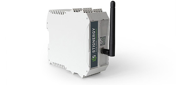
SEMS Terminal
SEMS system is decentralized and scalable. It consists on a set of modules called “terminals”(, a submeter and a gateway. Each terminal is) able to:
- measure the electrical parameters of a device (heat pump, refrigerator, oven …). The measured parameters are the instantaneous and RMS value of the voltage and the current. It also measures the active/reactive power, the cos φ … and much more.
- share together their measurements.
- execute an algorithm whose goal is to minimize the quarterly-hour peak.
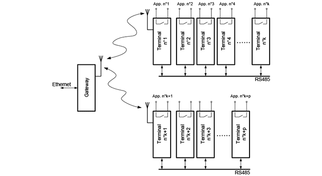
Only the largest energy consumers in the system are associated with a terminal. The system architecture is hierarchical and SEMS terminals are grouped into clusters. Typically, a cluster of terminals is often installed in each switchboard of the installation. Communication takes place in two stages:
- - RS485 communication between all terminals of a cluster
- - RS485 or radio communication between the Gateway and the cluster heads which are radio- equipped terminals.
Some clusters may be reduced to a single terminal if the monitored device is far away from the others and cannot be controlled from the switchboard. For example: an air conditioner or a ventilation machine located on the roof of the building. The structure is shown in the figure below:

Configuration structure of the SEMS terminals architecture
Technical Data of the SEMS Terminal
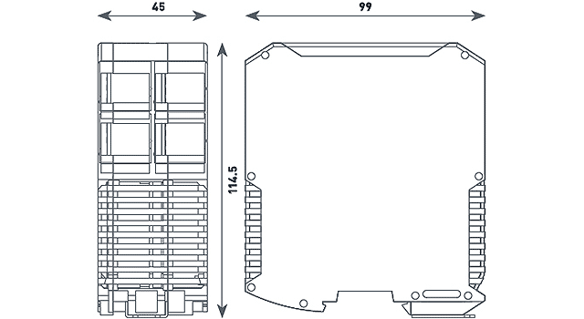
- Polyamide housing, light gray, DIN-rail mounting
- Flammability class UL 94 V0
- Terminals up to 32 poles, spring connection
- Communication: Radio 868 MHz ISM 500 mW, and / or RS485
- Energy measurement, single and three-phase, 3X240/400 VAC 50Hz
- For currents, I> 16A, connection with an external current transformer (CT) up to 1,500 A
- 3 internal control relays: contact capacity: 16A / 240 VAC. They can be used as well to drive external relays for currents I> 16 A
- 3 control lines of up to 40 VAC
- Storage of measured values (current, voltage, power, etc.) on an internal memory card.

SEMS Terminal


